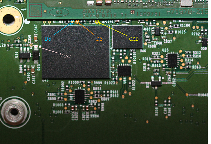
Need to use 1-bit SPI and prevent CPU from utilizing the EMMC. Not easy; though shorting CPU CLK seems like the most viable option.
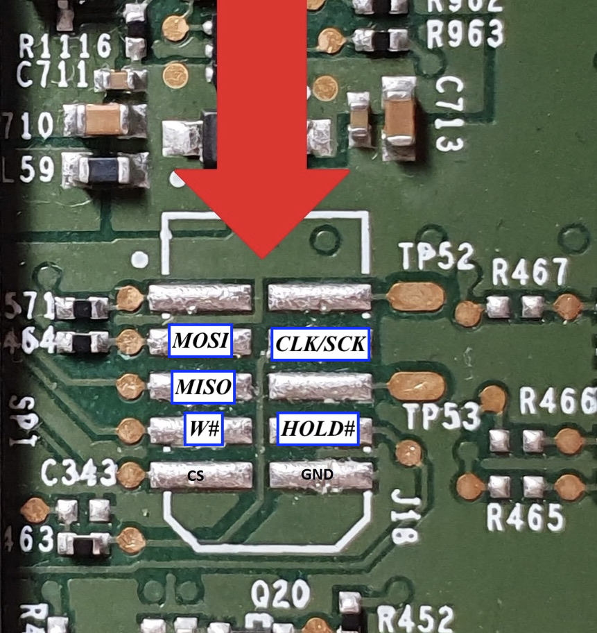
MCU SPI Flash Touchpoints
To dump this, you need to short the BMP RESET button header (or hold down the button), then power on the unit via the normal method. After a few seconds you will be able to read and write successfully.
Some board have headers if you’re lucky.
Attempting to dump the SPI while the unit is powered off but you provide voltage leads to many 0s in the start of the dump when reading; and failures in writing leading to the SPI only containing 0s. This is likely due to the SPI being read; thus why we must short the BMP RESET button.
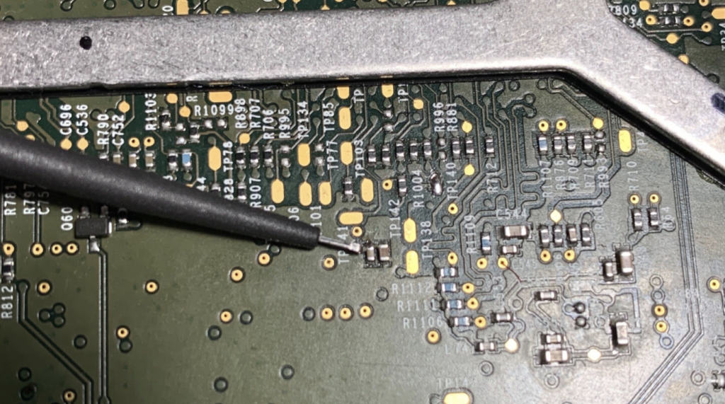
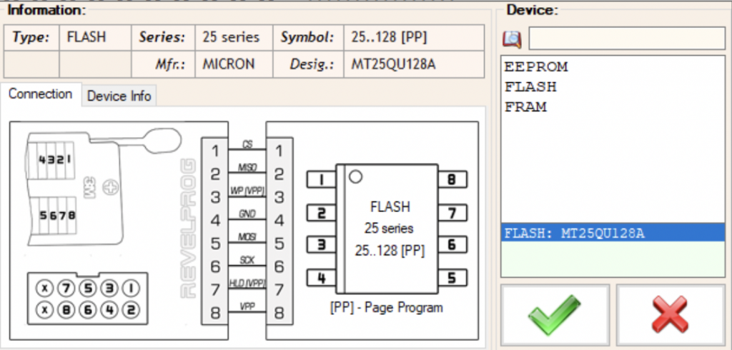
We need to provide 1.8v to this point. 1.9v may be needed due to voltage drop across components.Revelprog settings. Use 200mA overload protection as well, 50% write speed//clock frequency.
APE3 SPI Flash Touchpoints
There is a RESET button to the side of one of the SPI chips. I shorted this button and did not provide power to the unit normally when dumping the SPI successfully for both ape-a and ape-b.
Ask for ape3 Touchpoints – I did not contribute to finding them so I have some reservations sharing.
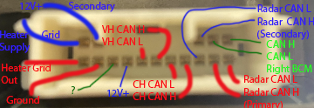
Pin 4+5+13 are inputs for 12V up to 5A.
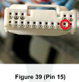
Pin 15 is ground.
Pins 9+10 are CH CAN H+L
11+12 are VH CAN H+L
Pins 1+2 CAN H/L Right Body Controller
Pins 7+6 are Primary CAN H/L to Radar
Pins 3+8 are Secondary CAN H/L to Radar
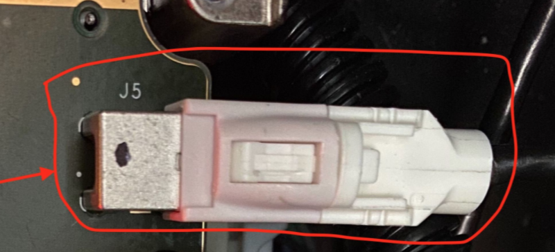
Connector which plugs in to the AP unit.
Pin counting is assumed to be left to right, then down and around. This may not be accurate but I think it is given the diagram.
AP Blue Connector
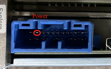
Connector X120 is the blue connector. It is used for power.
Pins 1+11 are eCall audio P+N
Pins 5+6 are PARTY CAN H+L
Pin 9 is 12V power in, up to 20A
Pin 18 is ground.
AP BroadR-Reach Connector
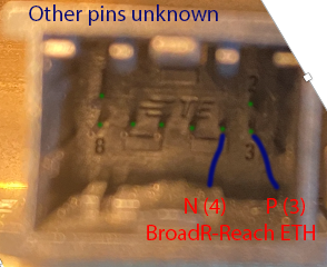
Connector X122 is used to connect MCU<->AP via BroadR-Reach. Connector is TE 2177586-1
Pin 3 is BR ETH P
Pin 4 is BR ETH N
Other pins are unknown and/or not used in production per wiring diagrams. From my brief look around, not much can be accessed here besides some UDP video feeds and the updater service.
This is also not present on HW3.2 as the connection was replaced with Rosenberger H-MTD cable to support gigabit BroadR-Reach (1000BASE-T1).
H-MTD Jumper Cable for MCU<->AP (MCU Side)
USB-C Debug Ethernet
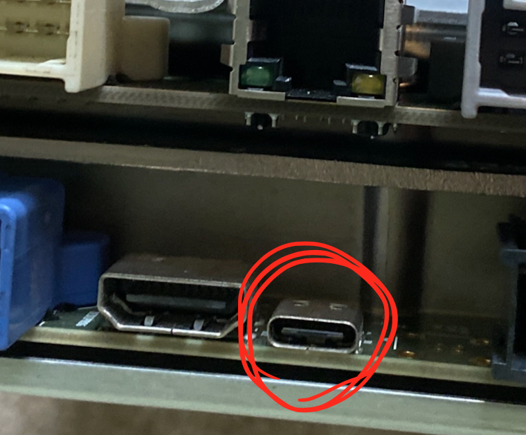
A USB-C connector which is not coded by Tesla is used for debug on the AP unit over Ethernet.
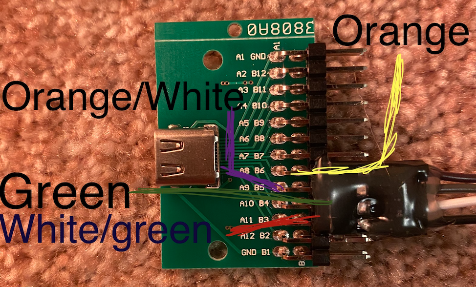
AP Debug EthernetUSB-C Breakout Board
When connected to a USB-C breakout board, these four pins are used for the Ethernet connection. The same four pins are mirrored on the other side of the board and provide the exact same access.
At least on production vehicles, absolutely nothing in accessible from this port. While an Ethernet connection is created, we are not able to access anything from this connector.
SPI Flash / JTAG ? (HDMI Connector)
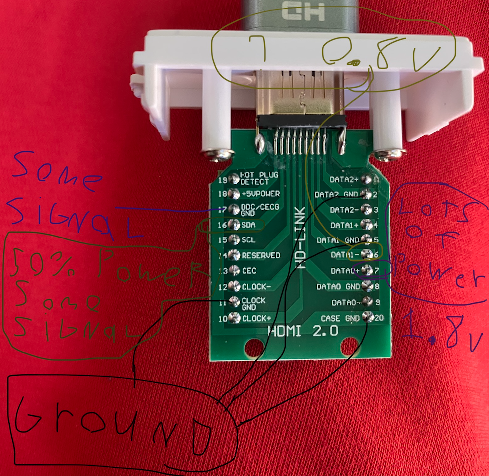
An HDMI connector is present to program the SPI Flash. I have not done much with this and I hear the flash is encrypted/checked, but this is some basic pin information
Limited information on the SPI flash over HDMI connection
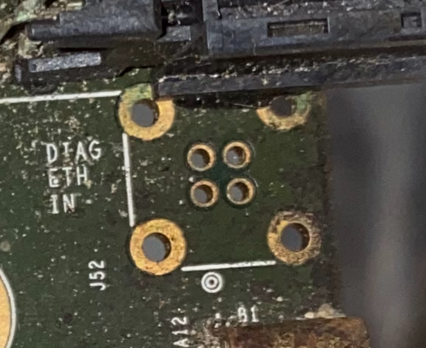
Diagnostic Ethernet
There is no header here but it is labeled Diag ETH In
Please excuse how filthy this board is. It was in a fire and then water damaged by the fire department.
Top Left     - Green
Top Right    - Green/White
Bottom Left  - Orange
Bottom Right - Orange/White
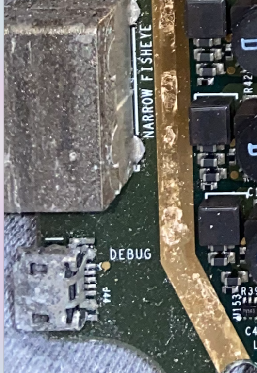
Micro-USB? (No Header)
Previously I’ve seen a micro-usb here with no header; presumably used for serial debugging.
Micro-USB on bottom. Or maybe micro-HDMI?
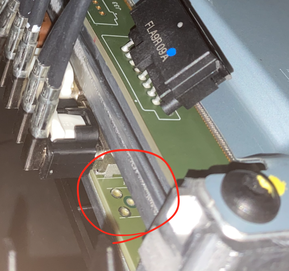
Right Repeater 2
This is a header for a second right repeater. Not used in any vehicles at the moment.