MCU Power Connector
This is connector X170
Part is Sumitomo 6098-5718
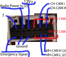
Pin 1+2 is CAN H+L (2)
Pin 4 is main power, always on.
Pin 5 is audio power in (2)
Pin 7+8 is VH-CAN H+L (2)
Pin 3+9 is PARTY CAN H+L (2)
Pins 10+11 are Ground
Pin 12 is Emergency Notification Signal Input
Pin 6 is unknown, possibly unused?
You can apply power to the +12V pin and ground to the case.
MCU Audio Connector
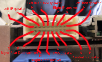
This is connector number X171. Part number is Sumitomo 6098-6203.
Pins 1+2 Left Door speaker P+N
Pins 9+10 Central IP speaker P+N
Pins 8+7 Left IP speaker P+N
Pins 4+3 Right IP speaker P+N
Pins 11+12 PWS audio P+N
Pins 14+13 Right door speaker P+N
Pins 5+6 Left rear door speaker
Pins 16+15 Right rear door speaker
Not much of interest to me here.
MCU RJ45 – Fast Ethernet
This is info on the MCU connector which is a standard RJ45 Fast Ethernet port. Removing the one piece of trim held in by 5 clips near the passenger’s feet allows us to connect with not too much trouble.
The drivers footwell port provides the same access. Info on building a harness for that port is here. Actual connector can be bought with pins here.
CID:        192.168.90.100 #A.K.A. MCU
IC:         192.168.90.101 #Not Present in 3/Y
Gateway:    192.168.90.102
AP:         192.168.90.103
AP-?:       192.168.90.104 #Seen in HW3
APE-B:      192.168.90.105
Tuner:      192.168.90.30
Diagnostic: 192.168.90.125 #Used for connecting to Driver's footwell
To connect, set your IP to 192.168.90.125 and subnet mask to 255.255.255.0. It is not possible to reach other devices on the network due to seceth rules unfortunately, but we can see that ports 22 (ssh) and 8080 (http) are open on the CID/MCU at 192.168.90.100.
We can attempt to reach ssh on the MCU at port 22. Auth is by certificate only though, and we obviously do not have the certificates needed; nor are they stored in the firmware files. The ssh version used is 7.9 as per firmware version 2021.4.18.10.
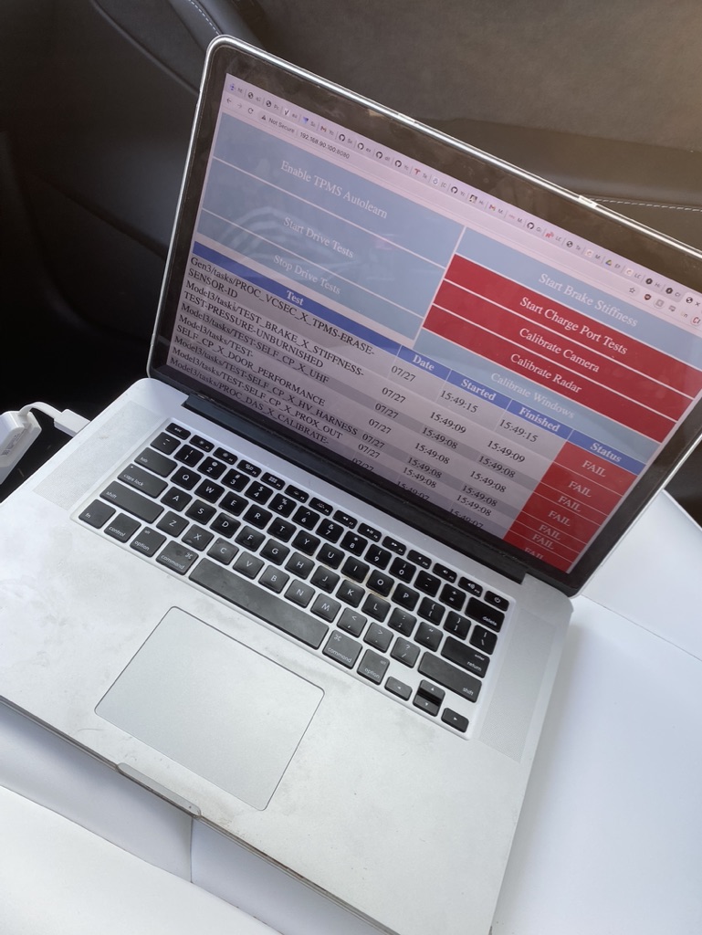
We can reach a front-facing page for the ODIN service at the HTTP interface on http port 8080 of the MCU, specifically at http://192.168.90.100:8080/. A number of functions (presumably used in the factory) are listed. None of them work though, as an authentication token is need to run nearly any ODIN function.
BroadR-Reach
HW2.5 -> HW3 (maybe including 3.1) use 100BASE-T1 BroadR-Reach protocol for communication between both the AP and the MCU, and the radio and the MCU.
X172 is the black connector that goes into the AP unit. The connector is TE 2177587-1
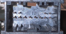
Pin 1 BR Eth P (AP)
Pin 2 BR ETH N (AP)
Pin 11 BR Eth N (Radio)
Pin 12 BR Eth P (Radio)
Pines 3+4 are audio to overhead speaker
Pins 7-10 are the Drivers Diag ETH Port
Pins 1 and 2 are not used on HW3.2 as it uses Rosenberger H-MTD instead. This is for Gigabit BroadR-Reach, or 1000BASE-T1. A higher-end adapter is required.
If connecting to the AP interface, set your IP address as 192.168.90.103. The ice-updater is accessible at port 20564 of the MCU. One can also access some ports assigned for autopilot functions.
Tuner interface (192.168.90.30) can also access ice-updater, ssh on the MCU, and port 5555 (something radio related?). For both connections, no access to the gateway is provided.
eCall / Emergency Connector
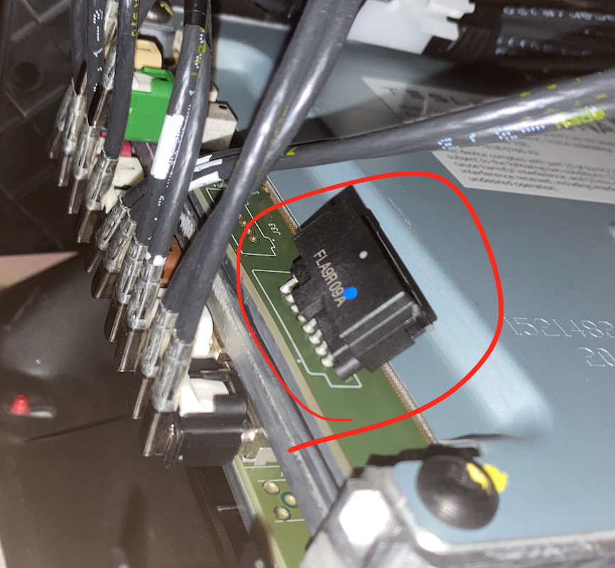
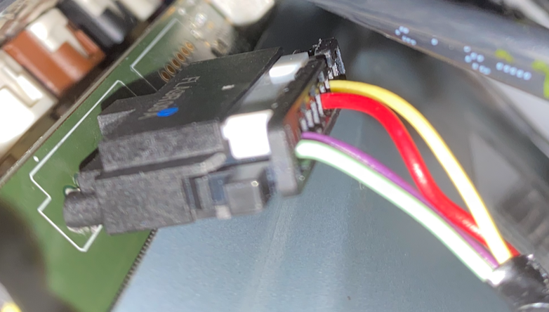
This is connector X173.
Pin 1 (green)   - Emergency Audio Out (N)
Pin 2 (violet)  - Emergency Audio Out (P)
Pin 6 (red)     - eCall Standby Power (+)
Pin 8 (yellow)  - RCM ENS In (eCall Passthrough)
This connector was introduced in HW3.0. By default, it is not connected on cars outside of Europe; though it is present.
FAKRA HSD Linking MCU and AP2.5

X800-H on AP to X859-H on MCU is the Fakra HSD port that connects the MCU and the AP units to send video. Just use Fakra HSD type-Z as its universal.
From what I hear from sources, this may be a normal Ethernet connection that can be tapped in to. Hopefully applies to all Fakra HSD connectors? I do not have a unit that uses this to confirm.
Connecting the Display
X860 connects the MCU to the display.
Pin 1 - 12v power (separate from Fakra HSD)
Pin 2 - ground (separate from Fakra HSD)
Pins 3-6 are used to transmit video
Must be connected before booting to work. Pin 1 is closer to the edge of the MCU, pin 2 is closer to the center.