So you’ve decided you’re going to start tinkering and want to get a unit on your bench? While some things are obvious to me now, they weren’t when I had first started this journey. So hopefully this brief guide, which compiles already public information along with some tips I’ve learned, makes it easier for you to set up your unit on a bench.
I find it obligatory to shout out Lewurm who provided the initial public info to help get me set up, and @greentheonly on Twitter who answered some questions to help me get started, and then some 🙂
What you will need
The Model 3/Y computer. Couple hundred bucks on ebay, depending which HW version you obtain.
A 12V power supply. Unless you are planning to input fake CAN data into the MCU or AP unit, the amperage draw will be very low. I would recommend a 5amp power supply to power both units; though 2A should probably be enough.
Wires. I have a large number of Dupont wires which make things easier for plugging and unplugging from certain pins.
Heat-shrink tubing (various size pack). This will be how you connect to the odd-sized pins on the unit. Extremely useful given the odd-sized pins used on the computer. A lighter is sufficient to heat it.
(Recommended) Anti-static wrist strap. Don’t want to short anything, especially if you will be taking the covers off.
(Optional) Connectors – If you know what ports you want to connect to and you would like to use the connector designed for that port, order those ahead of time. Aliexpress is not known for their speed.
(Optional) A Touchscreen – I have not gotten this working yet though.
Getting Started
Ensure your power supply is NOT plugged in. Strip off the ends of positive and ground wires of your power supply.
Use heat-shrink tubing that is just slightly larger than the wire to cover all of the exposed positive wire, leaving the heat-shrink tubing slightly overhanging the ends of the wire. Apply heat and ensure the tubing still slightly overhangs the wire. Leave the ground wire as is.
Now get your power supply and wires in a position where there is little to no weight on the end of the wire that will plug into the MCU.
Apply your ground wire to the casing of the MCU. You can ground to a screw on the case, on the board, or on the grounding cable attached to the MCU (if provided with your unit). Ensure the ground connection is secure.
Finally, plug your heat-shrinked positive wire onto the pin highlighted below.
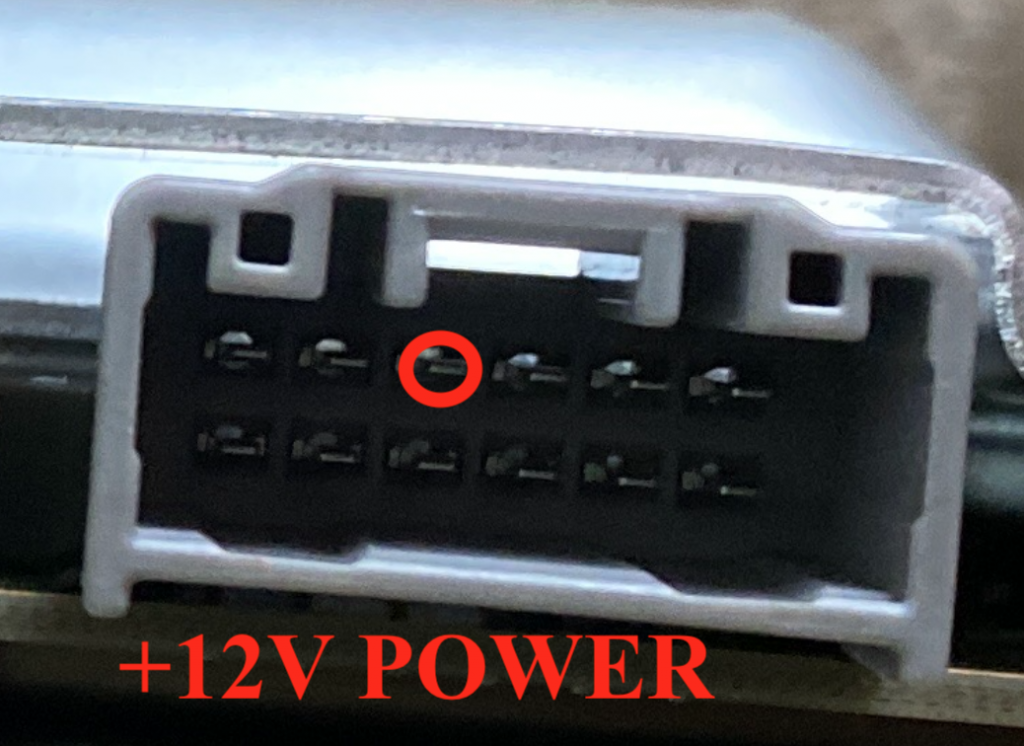
Ensure it fits snugly!
If you have a display, plug that in as well prior to powering on the unit (though mine has never actually turned on). When ready, plug in the power supply.
Confirming the Computer Works
After applying power, you can look through the spot circled below to check for flashing lights.
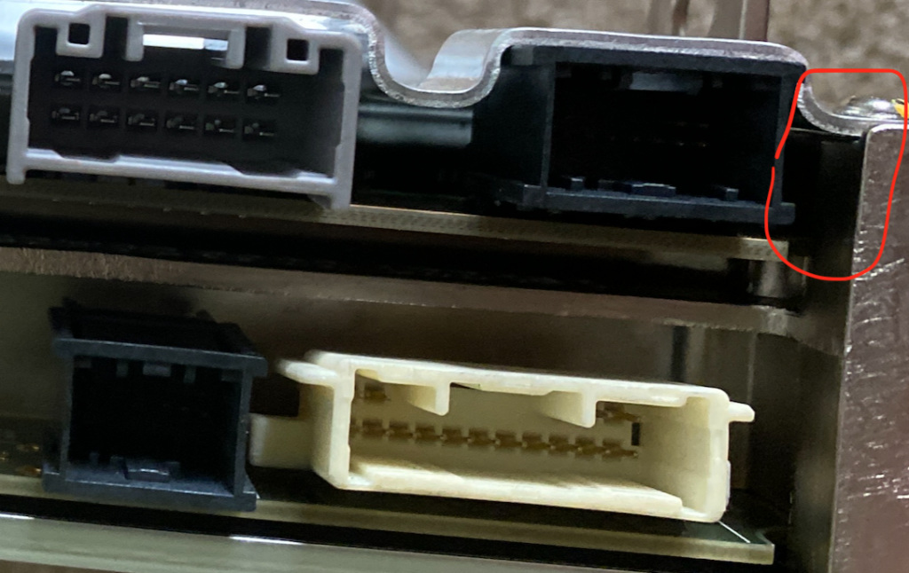
If the unit is powering on properly, you will see flashing red and later flashing red and green lights. You can also confirm these lights are flashing by removing the MCU cover. After a minute or two the display should turn on – tap it in case it does not come on or only comes on briefly.
You can alternatively confirm that the unit works by connecting to it via Ethernet over the RJ45 port, as discussed in more detail in this post. In brief, connect to the Ethernet port, set your IP to 192.168.90.125 and subnet mask to 255.255.255.0, then navigate to http://192.168.90.100:8080. If the page loads, the MCU works. It may take up to a minute for this to work after applying power.
That’s it! Your unit is powered on and ready to be toyed with. Have fun, and let me know if you find anything cool! 🙂