This content is password protected. Please enter a password to view.
Author: Analytic.eth
Protected: Touchpoints
Tuner Connector Information
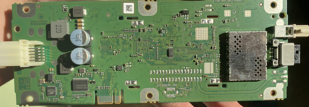
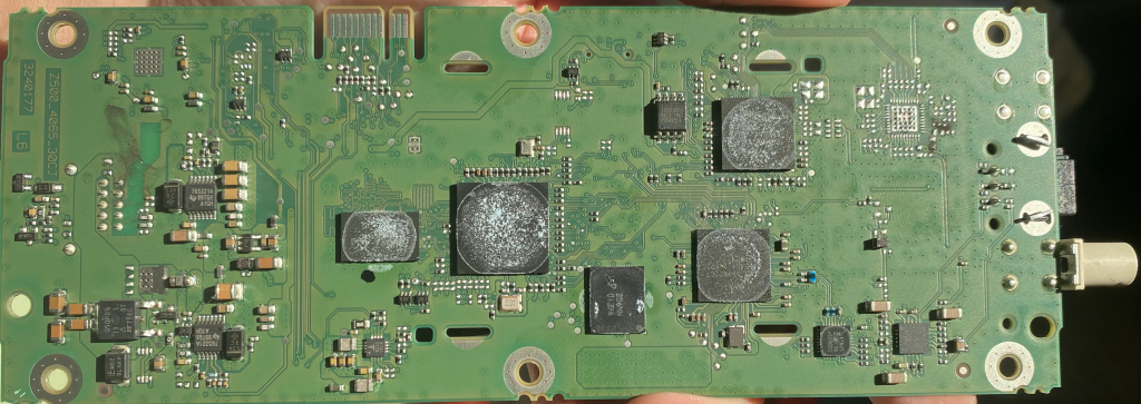
PCB Photos
Main Connector
This is connector X562
Part is TE 2302475-2
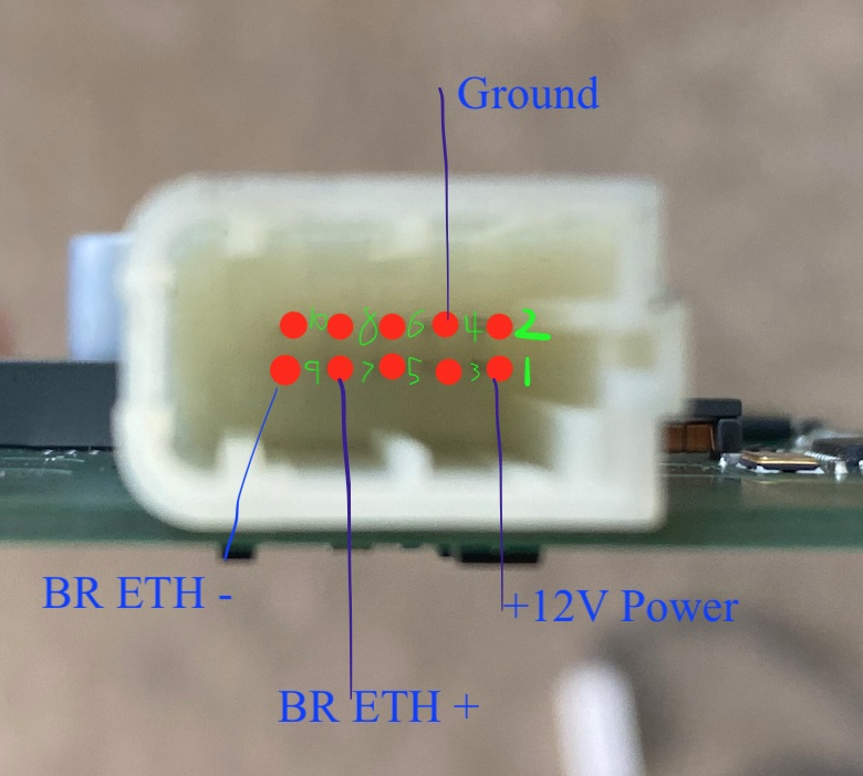
Pin 1 is + Power In
Pin 4 is Ground
Pin 7 is BR ETH +
Pin 9 is BR ETH -
You can apply power to the +12V pin and ground to the case.
Unused Black Connector
X815 is the black connector on the other side of the tuner.
The connector part number is Unknown
This connector is not used in production.
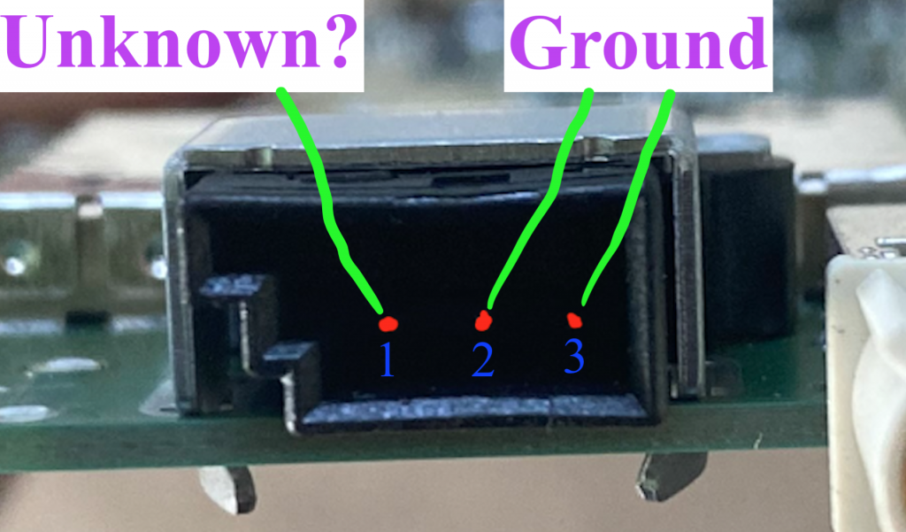
Pin 1 is Unknown
Pin 2 is Ground
Pin 3 is Ground
Tuner Antennae
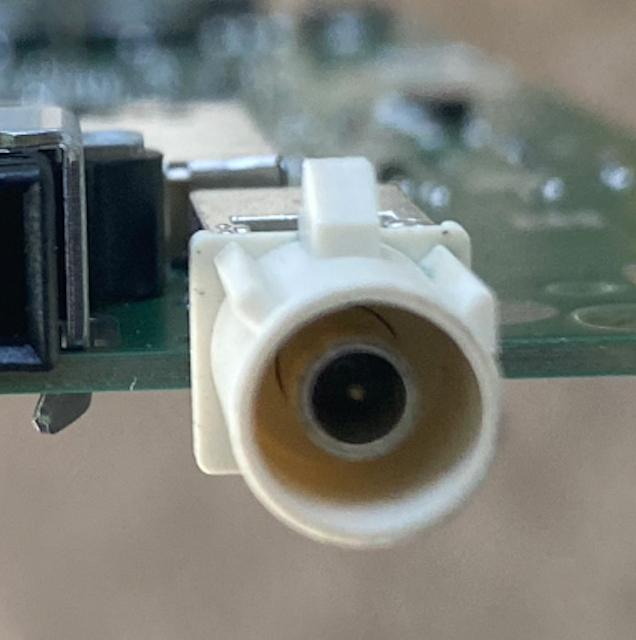
This is connector X818, next to the unused connector described above.
Looks like a normal Fakra antenna plug as the other antennae are.
Pin 1 is FM/DAB (2) Input
Shield is GroundExploring Service Mode Plus
Entering Service Mode Plus
In order to enter Service Mode Plus, one either needs root access (good luck) or a 24-hour authorization token. For this exploration, I obtained a tbx-external (the lowest level) authorization token, which enabled some diagnostic operations and entering Service Mode Plus. Do not ask me for an authorization token. Besides what is noted below, everything else operates the same as normal Service Mode.
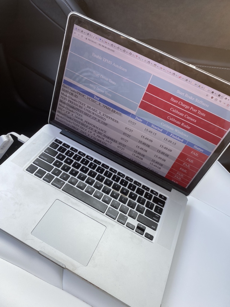
Systems Checks
This new systems checks menu is populated on the diagnostics page when clicking “Diagnostics” in Service Mode Plus. One can also click each item to see detailed responses and run individual tasks again.
Apologies for the awful blurring job.
CAN Viewer
This is the CAN Viewer unlocked when in Service Mode +. The CAN data one can read in this state is very limited, but it can provide some useful insight nonetheless.
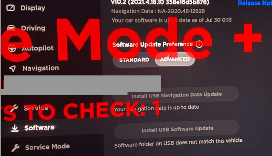
USB Updater
When in Service Mode Plus, two new options appear under the “Software” menu. The first allows one to install USB maps updates and the second installs firmware (CID/ICE/APE/Games). Details on how to perform these updates have yet to be determined and such information will need to be protected.
Protected: Experimenting with ICE-Updater [outdated]
Guide: Setting up a Bench Unit
So you’ve decided you’re going to start tinkering and want to get a unit on your bench? While some things are obvious to me now, they weren’t when I had first started this journey. So hopefully this brief guide, which compiles already public information along with some tips I’ve learned, makes it easier for you to set up your unit on a bench.
I find it obligatory to shout out Lewurm who provided the initial public info to help get me set up, and @greentheonly on Twitter who answered some questions to help me get started, and then some 🙂
What you will need
The Model 3/Y computer. Couple hundred bucks on ebay, depending which HW version you obtain.
A 12V power supply. Unless you are planning to input fake CAN data into the MCU or AP unit, the amperage draw will be very low. I would recommend a 5amp power supply to power both units; though 2A should probably be enough.
Wires. I have a large number of Dupont wires which make things easier for plugging and unplugging from certain pins.
Heat-shrink tubing (various size pack). This will be how you connect to the odd-sized pins on the unit. Extremely useful given the odd-sized pins used on the computer. A lighter is sufficient to heat it.
(Recommended) Anti-static wrist strap. Don’t want to short anything, especially if you will be taking the covers off.
(Optional) Connectors – If you know what ports you want to connect to and you would like to use the connector designed for that port, order those ahead of time. Aliexpress is not known for their speed.
(Optional) A Touchscreen – I have not gotten this working yet though.
Getting Started
Ensure your power supply is NOT plugged in. Strip off the ends of positive and ground wires of your power supply.
Use heat-shrink tubing that is just slightly larger than the wire to cover all of the exposed positive wire, leaving the heat-shrink tubing slightly overhanging the ends of the wire. Apply heat and ensure the tubing still slightly overhangs the wire. Leave the ground wire as is.
Now get your power supply and wires in a position where there is little to no weight on the end of the wire that will plug into the MCU.
Apply your ground wire to the casing of the MCU. You can ground to a screw on the case, on the board, or on the grounding cable attached to the MCU (if provided with your unit). Ensure the ground connection is secure.
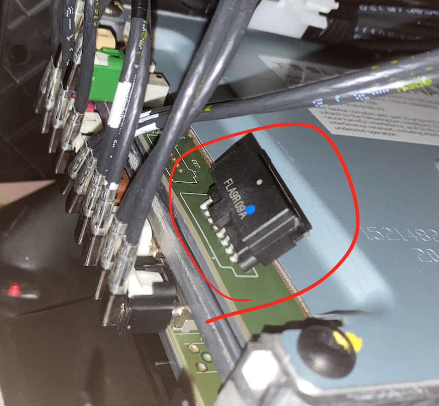
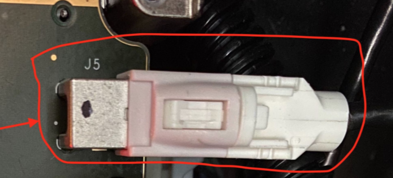
Finally, plug your heat-shrinked positive wire onto the pin highlighted below.
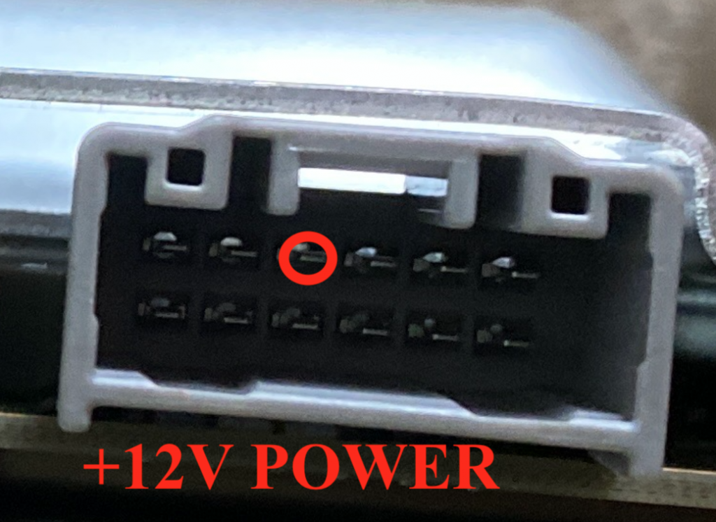
Ensure it fits snugly!
If you have a display, plug that in as well prior to powering on the unit (though mine has never actually turned on). When ready, plug in the power supply.
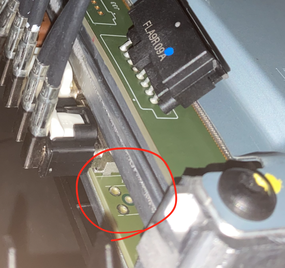
Confirming the Computer Works
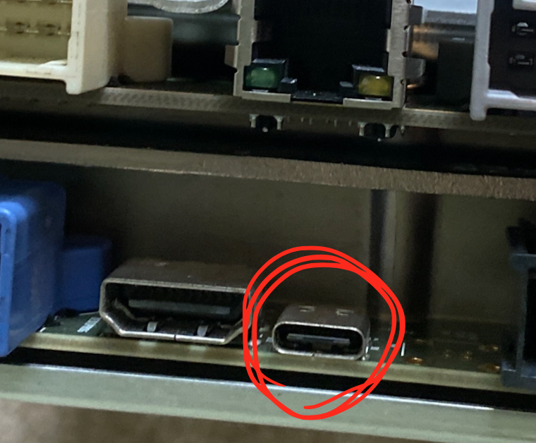
After applying power, you can look through the spot circled below to check for flashing lights.
If the unit is powering on properly, you will see flashing red and later flashing red and green lights. You can also confirm these lights are flashing by removing the MCU cover. After a minute or two the display should turn on – tap it in case it does not come on or only comes on briefly.
You can alternatively confirm that the unit works by connecting to it via Ethernet over the RJ45 port, as discussed in more detail in this post. In brief, connect to the Ethernet port, set your IP to 192.168.90.125 and subnet mask to 255.255.255.0, then navigate to http://192.168.90.100:8080. If the page loads, the MCU works. It may take up to a minute for this to work after applying power.
That’s it! Your unit is powered on and ready to be toyed with. Have fun, and let me know if you find anything cool! 🙂
MCU Connector Information
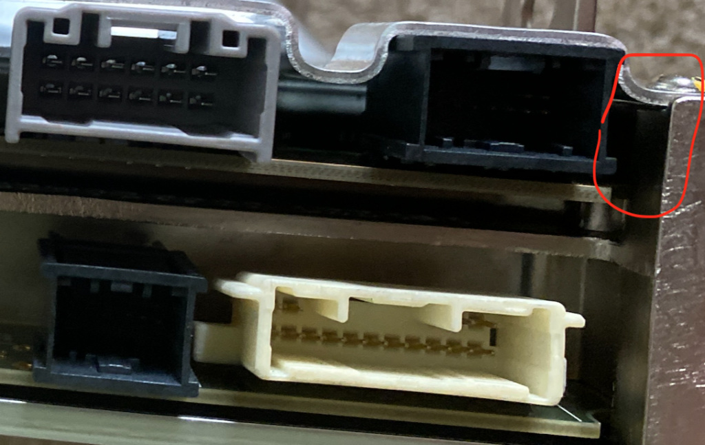
MCU Power Connector
This is connector X170
Part is Sumitomo 6098-5718
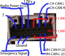
Pin 1+2 is CAN H+L (2)
Pin 4 is main power, always on.
Pin 5 is audio power in (2)
Pin 7+8 is VH-CAN H+L (2)
Pin 3+9 is PARTY CAN H+L (2)
Pins 10+11 are Ground
Pin 12 is Emergency Notification Signal Input
Pin 6 is unknown, possibly unused?
You can apply power to the +12V pin and ground to the case.
MCU Audio Connector
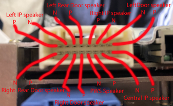
This is connector number X171. Part number is Sumitomo 6098-6203.
Pins 1+2 Left Door speaker P+N
Pins 9+10 Central IP speaker P+N
Pins 8+7 Left IP speaker P+N
Pins 4+3 Right IP speaker P+N
Pins 11+12 PWS audio P+N
Pins 14+13 Right door speaker P+N
Pins 5+6 Left rear door speaker
Pins 16+15 Right rear door speaker
Not much of interest to me here.
MCU RJ45 – Fast Ethernet
This is info on the MCU connector which is a standard RJ45 Fast Ethernet port. Removing the one piece of trim held in by 5 clips near the passenger’s feet allows us to connect with not too much trouble.
The drivers footwell port provides the same access. Info on building a harness for that port is here. Actual connector can be bought with pins here.
CID:        192.168.90.100 #A.K.A. MCU
IC:         192.168.90.101 #Not Present in 3/Y
Gateway:    192.168.90.102
AP:         192.168.90.103
AP-?:       192.168.90.104 #Seen in HW3
APE-B:      192.168.90.105
Tuner:      192.168.90.30
Diagnostic: 192.168.90.125 #Used for connecting to Driver's footwell
To connect, set your IP to 192.168.90.125 and subnet mask to 255.255.255.0. It is not possible to reach other devices on the network due to seceth rules unfortunately, but we can see that ports 22 (ssh) and 8080 (http) are open on the CID/MCU at 192.168.90.100.
We can attempt to reach ssh on the MCU at port 22. Auth is by certificate only though, and we obviously do not have the certificates needed; nor are they stored in the firmware files. The ssh version used is 7.9 as per firmware version 2021.4.18.10.
We can reach a front-facing page for the ODIN service at the HTTP interface on http port 8080 of the MCU, specifically at http://192.168.90.100:8080/. A number of functions (presumably used in the factory) are listed. None of them work though, as an authentication token is need to run nearly any ODIN function.
BroadR-Reach
HW2.5 -> HW3 (maybe including 3.1) use 100BASE-T1 BroadR-Reach protocol for communication between both the AP and the MCU, and the radio and the MCU.
X172 is the black connector that goes into the AP unit. The connector is TE 2177587-1
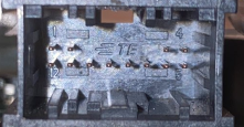
Pin 1 BR Eth P (AP)
Pin 2 BR ETH N (AP)
Pin 11 BR Eth N (Radio)
Pin 12 BR Eth P (Radio)
Pines 3+4 are audio to overhead speaker
Pins 7-10 are the Drivers Diag ETH Port
Pins 1 and 2 are not used on HW3.2 as it uses Rosenberger H-MTD instead. This is for Gigabit BroadR-Reach, or 1000BASE-T1. A higher-end adapter is required.
If connecting to the AP interface, set your IP address as 192.168.90.103. The ice-updater is accessible at port 20564 of the MCU. One can also access some ports assigned for autopilot functions.
Tuner interface (192.168.90.30) can also access ice-updater, ssh on the MCU, and port 5555 (something radio related?). For both connections, no access to the gateway is provided.
eCall / Emergency Connector
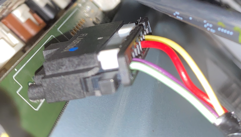
This is connector X173.
Pin 1 (green)   - Emergency Audio Out (N)
Pin 2 (violet)  - Emergency Audio Out (P)
Pin 6 (red)     - eCall Standby Power (+)
Pin 8 (yellow)  - RCM ENS In (eCall Passthrough)
This connector was introduced in HW3.0. By default, it is not connected on cars outside of Europe; though it is present.
FAKRA HSD Linking MCU and AP2.5

X800-H on AP to X859-H on MCU is the Fakra HSD port that connects the MCU and the AP units to send video. Just use Fakra HSD type-Z as its universal.
From what I hear from sources, this may be a normal Ethernet connection that can be tapped in to. Hopefully applies to all Fakra HSD connectors? I do not have a unit that uses this to confirm.
Connecting the Display
X860 connects the MCU to the display.
Pin 1 - 12v power (separate from Fakra HSD)
Pin 2 - ground (separate from Fakra HSD)
Pins 3-6 are used to transmit video
Must be connected before booting to work. Pin 1 is closer to the edge of the MCU, pin 2 is closer to the center.
Connector Information – Autopilot Unit
AP White Connector
For AP connector X121 is used for CAN.
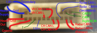
Pin 4+5+13 are inputs for 12V up to 5A.
Pin 15 is ground.
Pins 9+10 are CH CAN H+L
11+12 are VH CAN H+L
Pins 1+2 CAN H/L Right Body Controller
Pins 7+6 are Primary CAN H/L to Radar
Pins 3+8 are Secondary CAN H/L to Radar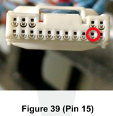
Pin counting is assumed to be left to right, then down and around. This may not be accurate but I think it is given the diagram.
AP Blue Connector
Connector X120 is the blue connector. It is used for power.
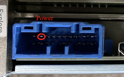
Pins 1+11 are eCall audio P+N
Pins 5+6 are PARTY CAN H+L
Pin 9 is 12V power in, up to 20A
Pin 18 is ground.
AP BroadR-Reach Connector
Connector X122 is used to connect MCU<->AP via BroadR-Reach. Connector is TE 2177586-1
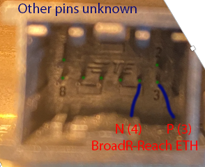
Pin 3 is BR ETH P
Pin 4 is BR ETH N
Other pins are unknown and/or not used in production per wiring diagrams. From my brief look around, not much can be accessed here besides some UDP video feeds and the updater service.
This is also not present on HW3.2 as the connection was replaced with Rosenberger H-MTD cable to support gigabit BroadR-Reach (1000BASE-T1).
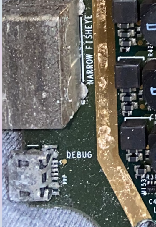
USB-C Debug Ethernet
A USB-C connector which is not coded by Tesla is used for debug on the AP unit over Ethernet.
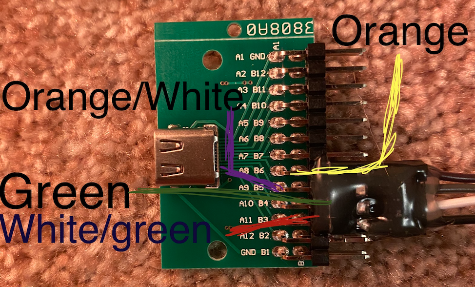
When connected to a USB-C breakout board, these four pins are used for the Ethernet connection. The same four pins are mirrored on the other side of the board and provide the exact same access.
At least on production vehicles, absolutely nothing in accessible from this port. While an Ethernet connection is created, we are not able to access anything from this connector.
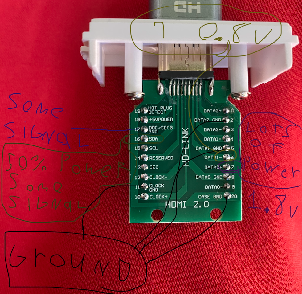
SPI Flash / JTAG ? (HDMI Connector)
An HDMI connector is present to program the SPI Flash. I have not done much with this and I hear the flash is encrypted/checked, but this is some basic pin information
Diagnostic Ethernet
There is no header here but it is labeled Diag ETH In
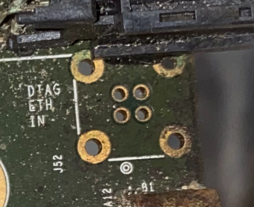
Top Left     - Green
Top Right    - Green/White
Bottom Left  - Orange
Bottom Right - Orange/White
Micro-USB? (No Header)
Previously I’ve seen a micro-usb here with no header; presumably used for serial debugging.
Right Repeater 2
This is a header for a second right repeater. Not used in any vehicles at the moment.